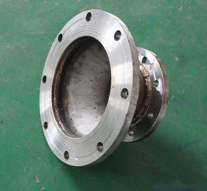
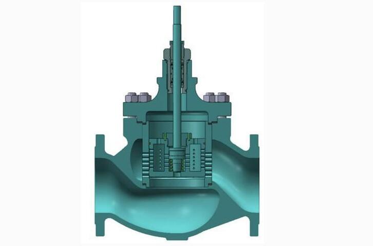
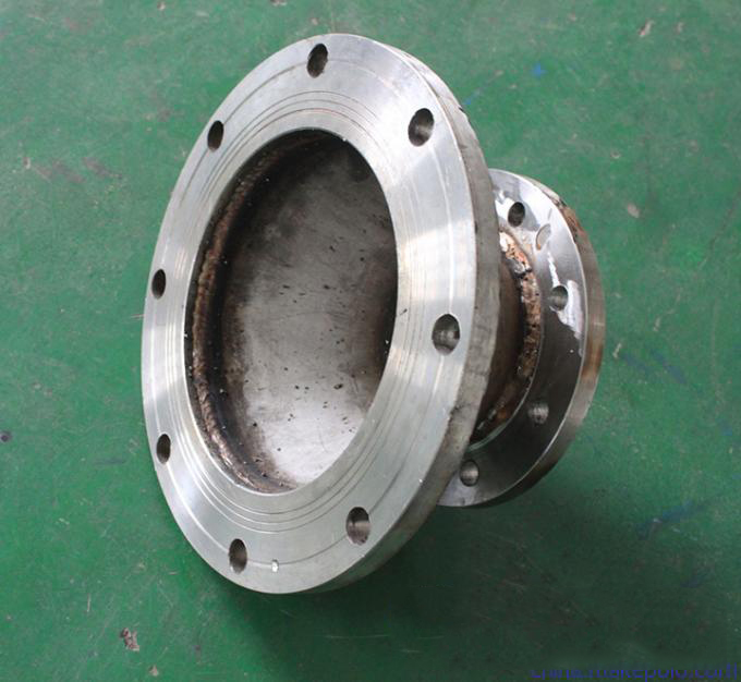
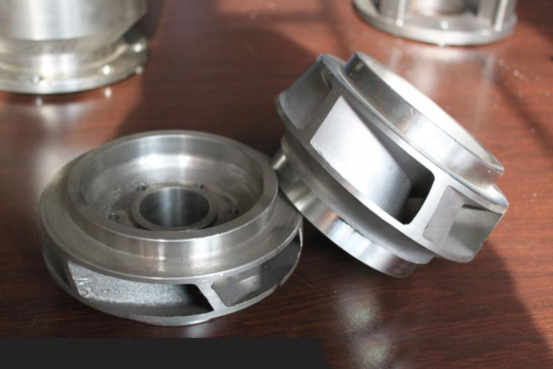
1. Remove the protective cover on both sides of the flange, the valve is fully open in the state to wash clean.
2. Before installation should be required by the signal (electric or pneumatic) to carry out the whole test (to prevent the impact of transport vibration caused by the use of performance), qualified rear line can be installed (wiring according to the electric actuator line diagram).
3. Prepare and remove the remaining impurities in the clean piping (which may damage the valve seat and ball) before connecting the pipe to the pipe.
4. During the installation, please do not use the valve body part as a lifting point, to avoid damage to the actuator and accessories.
5. This type of valve should be installed in the horizontal direction or vertical direction of the pipe.
6. Install the pipeline near the falls, or to withstand external force phenomenon, can use pipe support or supports pipeline to eliminate the deviation.
7. After connecting with the pipe, use the specified torque cross locking flange connection bolt.
Other technical parameter notes:
1. Forms of connection: thread, flange, welding, clip, etc.
2. Transmission mode: manual, worm gear transmission, gear transmission, pneumatic, electric, etc.
3. Caliber from DN6-DN600; pressure from 1.0MPA-64MPA; temperature -600
4. The materials are: carbon steel, stainless steel, alloy steel, chromium molybdenum steel, low temperature steel, ductile iron and other special steel;
5. Three or four ball valve on the pipeline can not only control the flow of media convergence, diversion, and the flow of the switch, but also can close any channel and make the other two channels connected.


